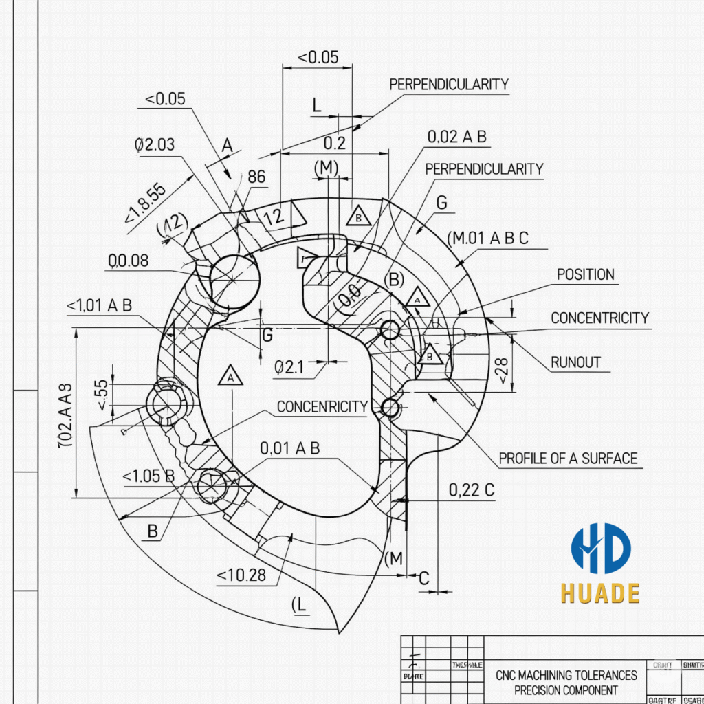
An engineering drawing with GD&T symbols and tolerance annotations, illustrating the precision of CNC machining tolerances.
In the world of precision manufacturing and rapid prototyping, there’s a term that separates a functional part from a failed one: CNC machining tolerances. Tolerances are the unsung heroes of engineering, defining the acceptable limits of variation for a part’s dimensions. While a part may appear perfectly made to the naked eye, its true quality is measured by how precisely it adheres to the design specifications—and that’s where tolerances come in.
This article provides a deep dive into CNC machining tolerances, moving beyond the basics to help you understand their importance, the different types, and how you can actively control them to ensure your prototypes are not just good, but perfect.
What are CNC Machining Tolerances?
At its core, a tolerance is a permissible range of deviation from a specified dimension. Every manufactured part has a nominal dimension (the ideal measurement specified in the design). However, due to the inherent physical limitations of machines, tools, and materials, it is impossible to produce a part that is exactly the nominal dimension every single time.
A tolerance is typically expressed as a plus/minus range (e.g., ±0.05mm), defining the upper and lower limits of an acceptable part. For a hole with a nominal diameter of 10mm, a tolerance of ±0.05mm means the acceptable diameter is anywhere between 9.95mm and 10.05mm. Any part falling outside this range is considered out of spec and must be rejected.
Understanding Tolerance Grades and GD&T
While simple plus/minus tolerances are common, the world of precision engineering uses a more sophisticated language known as Geometric Dimensioning and Tolerancing (GD&T). GD&T is a standardized system that uses a symbolic language to precisely define the size, form, orientation, and location of a part’s features. It allows for unambiguous communication between the designer, the machinist, and the quality inspector, ensuring everyone is on the same page.
ISO 2768 is another key standard that defines general tolerances for linear and angular dimensions, as well as for features without specific tolerances indicated on the drawing. It categorizes parts into different tolerance grades, such as:
- “f” (Fine): For very precise features where tight fits are required.
- “m” (Medium): The most common grade for general-purpose machining, suitable for most prototypes.
- “c” (Coarse): For less critical dimensions where a wide range of variation is acceptable.
- “v” (Very Coarse): For features where precision is not a concern, such as rough cuts.
Specifying a tolerance grade allows you to communicate the required level of precision for your part. A good engineer understands that not all features need tight tolerances; over-specifying precision on non-critical features will only increase machining time and cost.
How to Control Precision: From Design to Machining
Achieving the desired precision is a collaborative effort that begins long before the first cut is made. The key lies in careful planning and execution during both the design and machining phases.
Design Phase: The Role of a CAD Engineer
The decisions made during the CAD design phase have the most significant impact on a part’s manufacturability and final precision. As a designer, you are in control of specifying the correct tolerances for your part.
Here are some key design considerations:
- Specify Tolerances Strategically: Do not apply tight tolerances to every feature. Reserve them only for critical interfaces, mating surfaces, and areas where precision is essential for the part’s function.
- Design for Manufacturability (DFM): Consider the limitations of CNC tools and processes. Avoid deep, narrow pockets, very thin walls, and sharp internal corners. CNC tools are round, so they will always leave a radius in internal corners.
- Understand the Material: Different materials have different properties. Harder materials like tool steel are more difficult to machine to tight tolerances than softer materials like aluminum.
Understanding and correctly applying these principles in your design is the first step to achieving precision. To gain a broader perspective on the entire prototyping journey, from material selection to cost factors, we invite you to explore our ultimate guide on CNC machining tolerances.

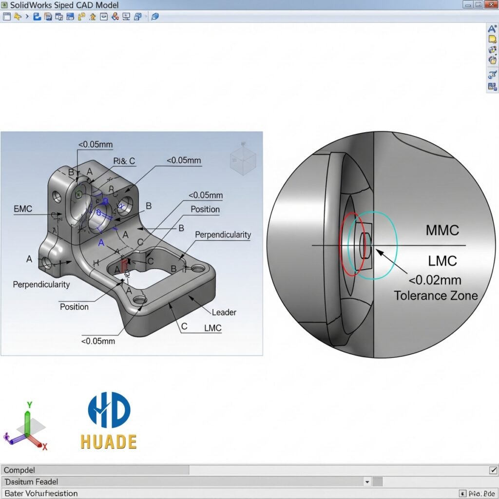
A comparison image of a CAD model with detailed tolerance design on the left and a magnified view of the tolerance zone on the right, highlighting precision in manufacturing.
Machining Phase: How the Operator Ensures Accuracy
Even with a perfect design, precision ultimately depends on the skill of the CNC machine operator and the capabilities of the machine itself.
Here are the key factors a machinist controls:
- Tooling and Machine Calibration: The machine’s spindle, cutting tools, and fixtures must be perfectly calibrated and in good condition. Worn-out tools can lead to inaccurate dimensions and poor surface finishes.
- Cutting Parameters: The operator must choose the correct cutting speed, feed rate, and depth of cut for the specific material and tool. Incorrect parameters can cause tool deflection, vibrations, and a loss of precision.
- Environmental Factors: Temperature and humidity can cause materials and even the machine itself to expand or contract slightly. A professional shop maintains a controlled environment to mitigate these effects.
The Relationship Between Tolerances, Cost, and Lead Time
This is a critical point for anyone commissioning a prototype. There is a direct, proportional relationship between tolerance requirements and the cost and lead time of a project.
- Tighter Tolerances = Higher Cost: To achieve a tighter tolerance, the machinist must use more precise tools, run the machine at slower speeds, and perform more frequent measurements and inspections. This requires more time and resources.
- Tighter Tolerances = Longer Lead Time: The meticulous process of achieving high precision means that each part will take longer to machine and inspect, extending the project timeline.
Choosing a medium tolerance grade (e.g., ISO 2768-m) for most non-critical features is a practical approach that balances quality with cost-effectiveness.
Conclusion
Tolerances are more than just numbers on a blueprint; they are the guarantee of a part’s quality and functionality. A deep understanding of CNC machining tolerances, from the basics of GD&T to the practical implications on cost and lead time, empowers you to design better, communicate more effectively with your manufacturing partner, and ultimately, bring a successful prototype to market.
At Dongguan Huade Precision Manufacturing Co., Ltd., our team of skilled engineers and machinists is dedicated to delivering parts that meet your exact specifications. We can help you navigate the complexities of tolerances and ensure every prototype we produce is a testament to precision.
To get started on your next precision prototyping project and discuss your tolerance requirements, visit our contact us page for a free quote.
